Wings of Silence YouTube :Japanese audio with English subtitles
Records tell the truth about the Japan Airlines Flight 123 crash : Omnibus
English subtitles
5. Technical examination results
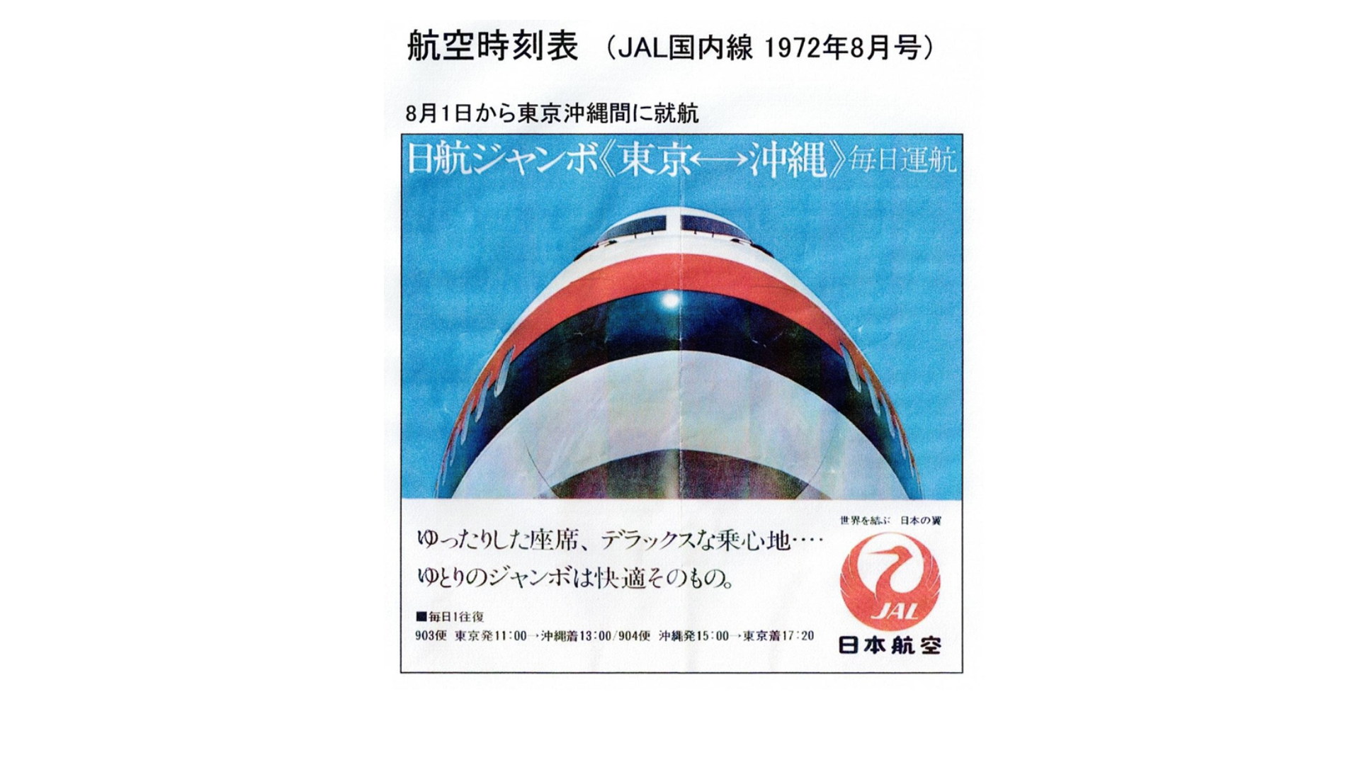
From here, I will sort out the causes of the failure process, focusing on individual data. JAL has launched LR aircraft on domestic flights since August 1972. Since the SR aircraft appeared in October 1973, the LR aircraft was used for the first service.
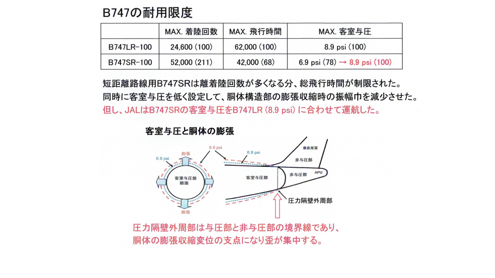
As I mentioned earlier, Boeing has set operational standards for SR aircraft as shown in this table. Instead of doubling the number of takeoffs and landings of SR aircraft, the flight time was reduced to about 70%, and most importantly, the in-flight pressurization was set to 6.9 psi, which is lower than 8.9 psi for international flights.
The purpose of reducing pressurization is to suppress the expansion of the aircraft and suppress the progression of fatigue during frequent operations. This means that SR aircraft cannot fly at fuel-efficient flight altitudes around 35,000 feet, limiting flight altitudes.
When SR aircraft finally go into service, JAL will prioritize economic efficiency and fly domestic flights at the same high altitude as international flights, except for short-haul routes, and will apply the same high in-flight pressurization to LR aircraft on all routes including short-haul flights. I think this decision is the beginning of a mistake.
It is noted that the fulcrum of the expansion and contraction movements during flight and on the ground is on the outer periphery of the rear pressure bulkhead. It is clear that the large expansion of 8.9 psi has a larger movement near the fulcrum, which is disadvantageous for repeated metal fatigue at the fulcrum.
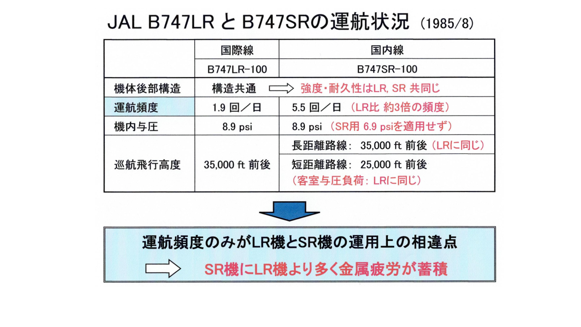
The flight status of LR and SR aircraft in the month of the accident is summarized in the table.
As mentioned above, the SR aircraft has repeatedly expanded and contracted to the same extent as the LR aircraft in all flights, regardless of the length of the flight distance.
It is clear to everyone that a lot of metal fatigue has accumulated on SR aircraft that operate about three times as often.
It should be remembered that the JA8119 still had old wound on the upper half of the pressure bulkhead. I will explain the flight frequency and flight altitude that the report did not mention with concrete data.
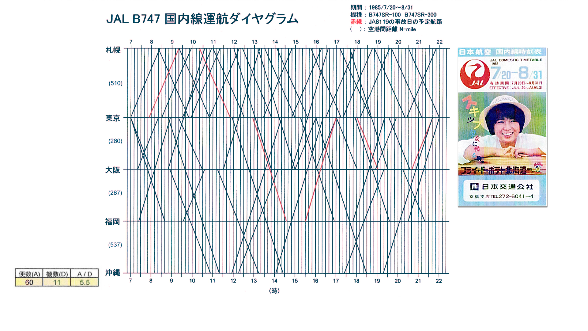
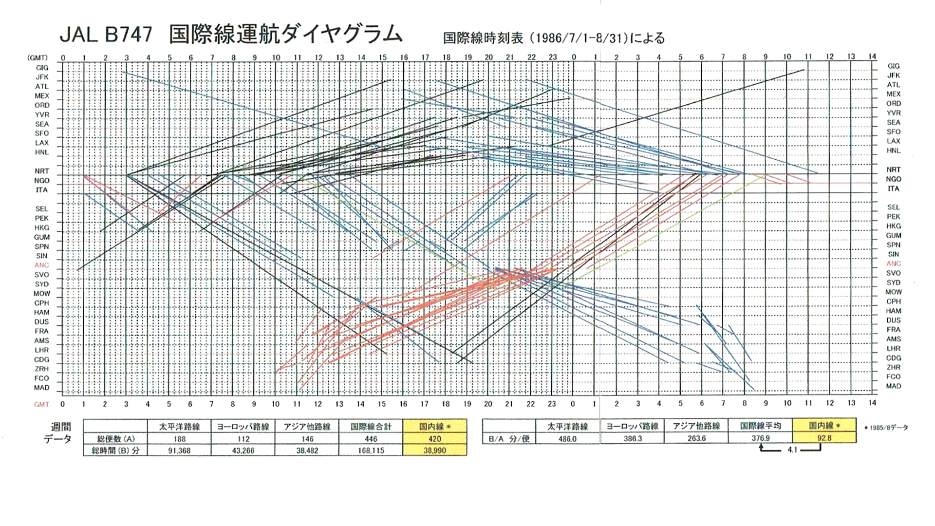
From my aviation timetable collection, I drew a diagram of the operation status of SR aircraft, and calculated the total number of flights and the number of operating aircraft. The SR aircraft took off and landed 5.5 times a day on average. JA8119 on the day of the accident, indicated by the red line, was scheduled to fly six times a day.
This is the diagram of the international LR aircraft at that time. The result was an average of 1.9 times a day for each aircraft to take off and land. From the data of the two diagrams, I grasped the fact that SR aircraft operate about three times as often as LR aircraft. Of course, JAL also knew this basic data.
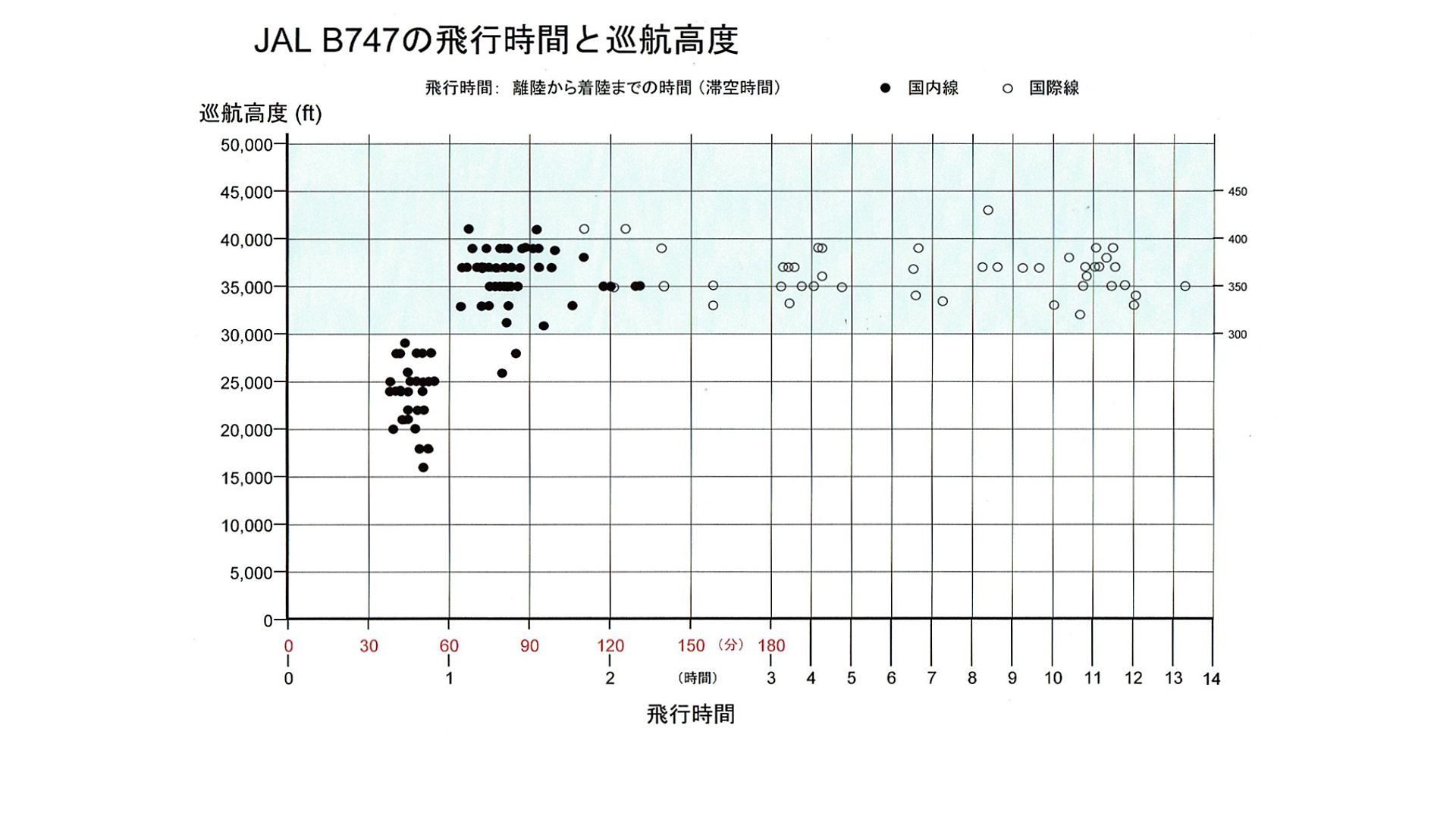
Next, consider the flight altitude. This figure shows the relationship between the flight time and flight altitude of JAL's B747. Black circles are domestic flights and white circles are international flights.
The data is the distribution of flight time and flight altitude based on the data of about 150 times of JAL B747 from my boarding record, and I asked the captain to fill in the data every time I boarded. From the data, it was found that SR aircraft on routes with a flight time of more than one hour fly around 35,000 feet at the same economic altitude as LR aircraft.
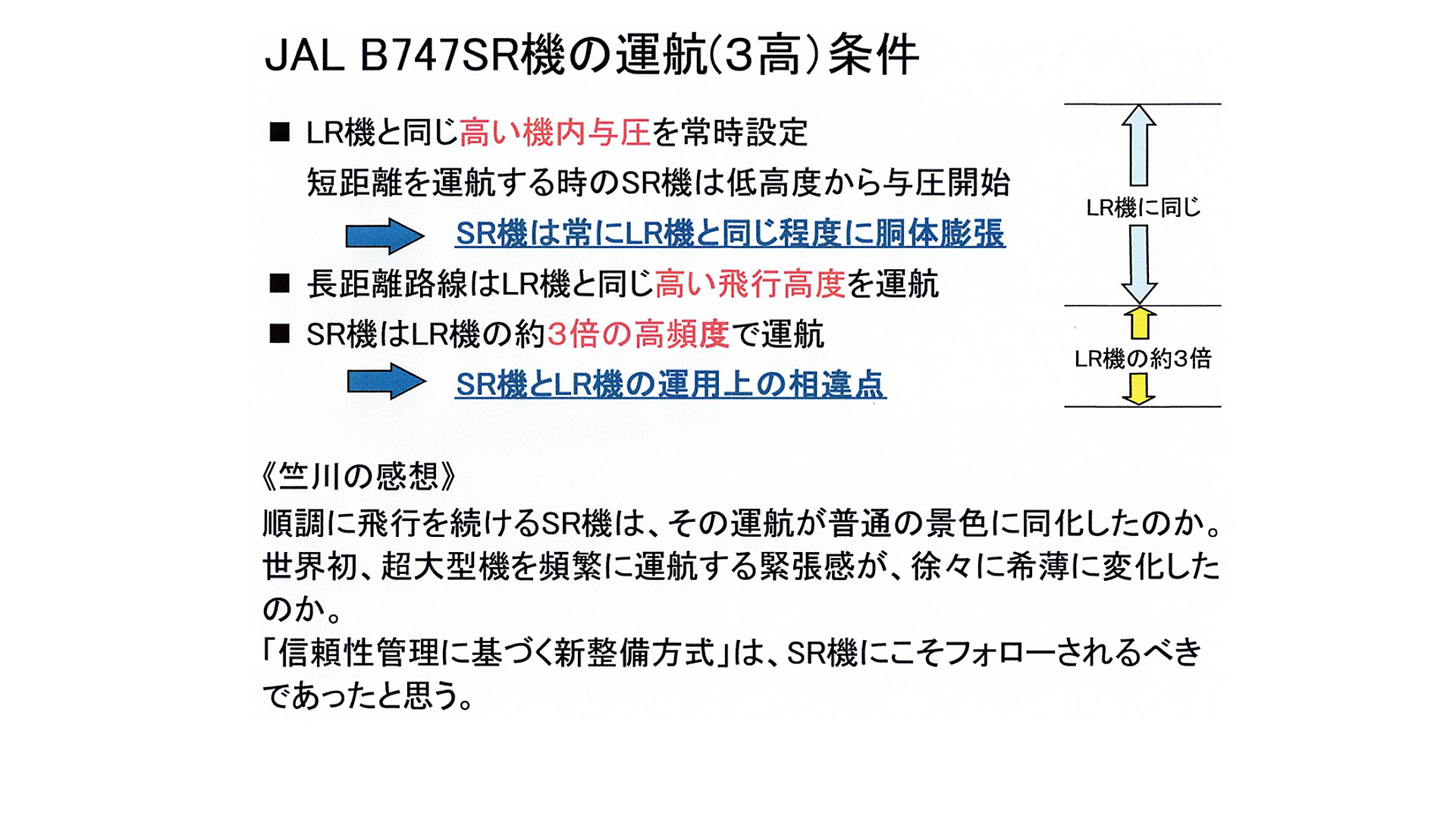
I will summarize the 3 heights of the SR aircraft. 3 high refers to 3 highs of high in-flight pressurization, high flight altitude, and high flight frequency.
3 High is an event in which the report did not touch on the mutual relationship. At that time, JAL advocated "courage to be called a coward" and "intense maintenance with a sigh". In 1983, JAL finally became the world's number one airline in terms of air transport volume.
Under such circumstances, the fact that the SR aircraft, which continued to operate smoothly, was forced to fly harshly became a normal scene, and the tension may have gradually diminished. It would be a shame if JAL, which operates the world's largest B747, was overconfident and unpredictable.
I think that the "new maintenance method based on reliability management" that was implemented jointly by each country at the beginning of the introduction of the B747 should have been focused on SR aircraft that operate three times more frequently. This must have been a consideration that only JAL can do.
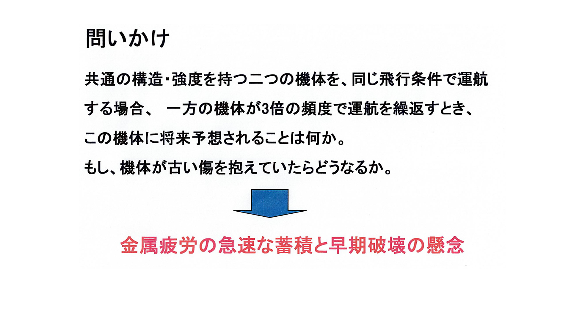
I asked in the series as follows.
"If two aircraft with the same structure and strength are operated under the same flight conditions, what do you think of this aircraft in the future when one aircraft repeats operations three times as often?" What if this aircraft had an old wound that hadn't been treated for a long time? The answer is clear.
In order to reinforce the certainty of the Jikusen theory, I will change the viewpoint of cause examination to a direction that no one has approached in the past.
I incorporated a unique element of tire wear into the failure analysis, and I was convinced that the B747 had the characteristics that easily induce this failure.
The airline pays the landing fee to the airport authorities. Similarly, they pay the tire supplier the tire usage fee. It is a tire leasing method that started in the United States in the 1970s. With this method, the condition of the tires is constantly grasped, and it is possible to follow a huge amount of data between tires, and the target is JAL B747.
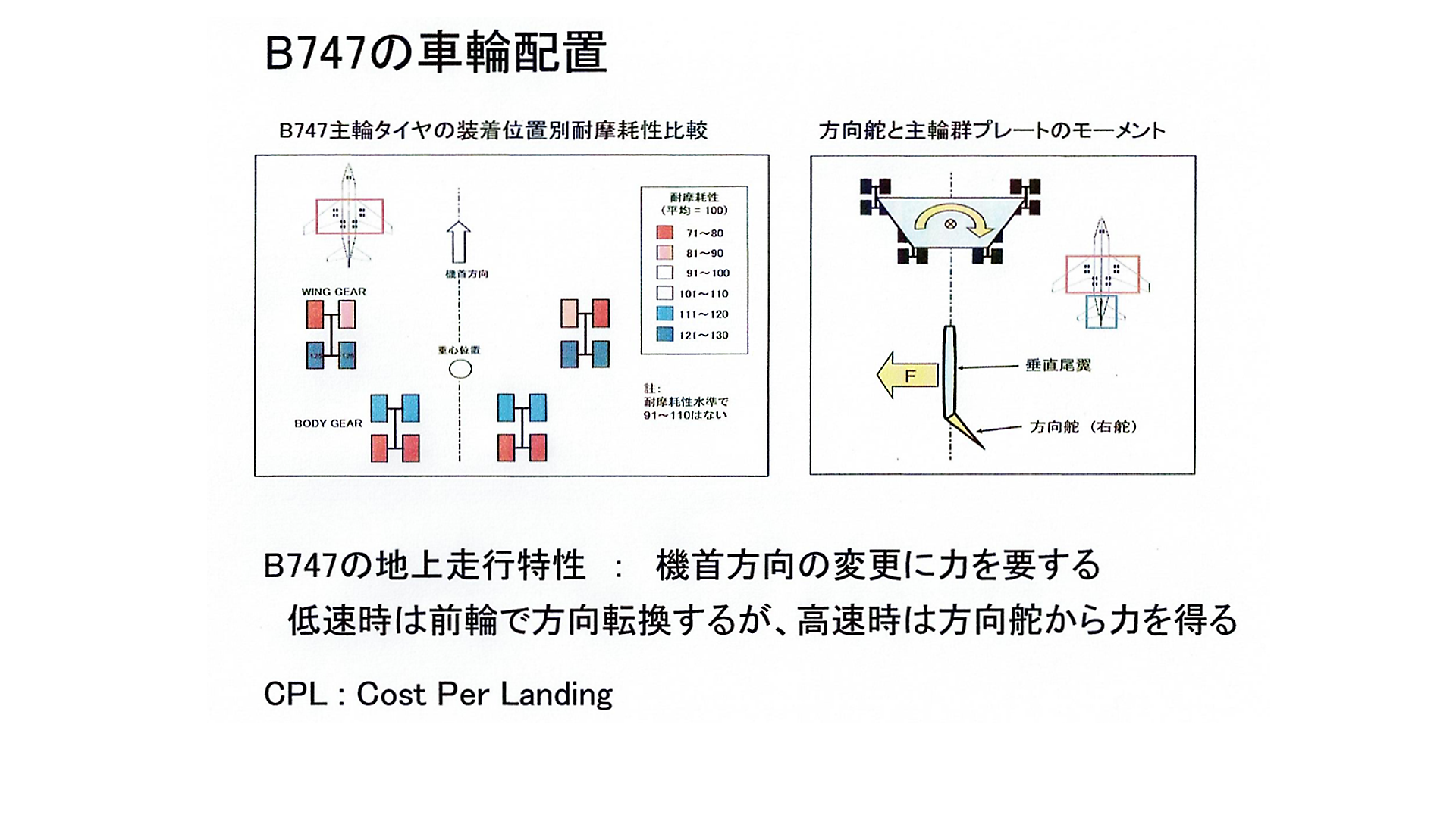
On the other hand, the leg structure of the B747 has unique ground running characteristics, and a unique tire wear condition is observed. As shown in the figure on the left, the actual wear of the B747 varies by about 50% depending on the tire mounting position. I refocused on the reason for this difference and the force around the pressure bulkhead.
The ground driving characteristics are that it requires a large amount of force to change the nose direction.
Airplanes use aerodynamics to steer to change direction when traveling on the ground at high speeds. The direction of rotation of the tire is fixed to the front. Therefore, when changing the nose direction due to crosswinds, the tires will be forced to skid. There is a difference in wear depending on the size of the slide.
If you replace a set of main wheels with roller skates fixed at the four corners as shown in the figure on the right, it is not easy to change the direction of the entire trapezoid with your feet on the ground. The plane is forcing it on the runway while sliding the tires.
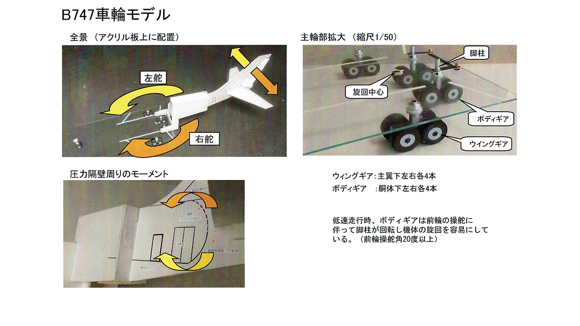
I made a model with moving blades and tires, and made an image of the actual site and considered it.
It forces the tire to skid when changing direction, but instead of slipping in one direction, the tire slides while rotating, reducing the coefficient of friction. Microscopically, slippage occurs on the tire surface. While traveling on the ground, the rudder of the vertical stabilizer must produce a powerful force that surpasses the skid resistance of the 18 tires.
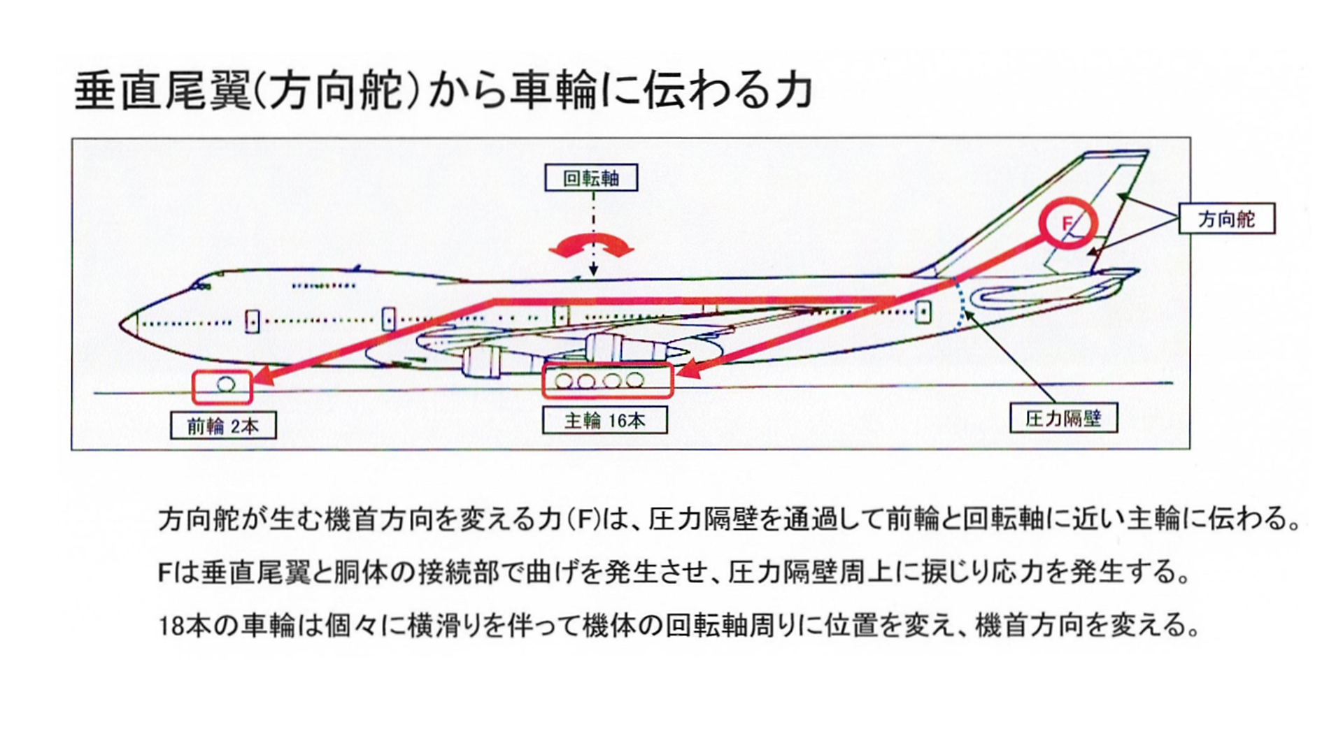
This figure is an image of the force transmitted from the vertical stabilizer to the wheels. When force F is generated from the rudder, bending and torsional stress are generated near the base of the vertical stabilizer. It is also near the upper mounting position of the pressure bulkhead.
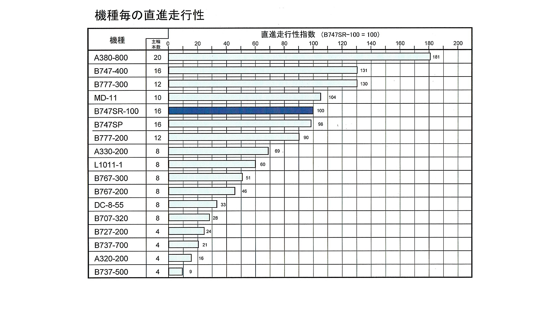
Lateral force is generated by the rudder at the top of the rear of the fuselage and is transmitted to the tires at the bottom of the fuselage via the top of the pressure bulkhead. When considering the force relationship near the outer circumference of the pressure bulkhead, I focused on the tendency of straight-line running performance for each aircraft.
This figure shows the directivity of straight running in the direction of travel with the SR aircraft as 100. It is replaced from the vertical stabilizer in the order of the required force F, and also in the order of the bending and torsional stress at the base of the vertical stabilizer.
Aircraft larger than SR aircraft are long-haul aircraft and are less likely to be a problem because of their low frequency of flight, but SR aircraft are by far the largest among short-haul aircraft.
The data show that the JA8119, which has accumulated strain on the upper part of the pressure bulkhead in the SR aircraft, has a high probability of fatigue failure.
Next, I would like to introduce the observation results of the fuselage skin tear line. The purpose is to consider the position of the gap created between the outer circumference of the pressure bulkhead and the fuselage skin.
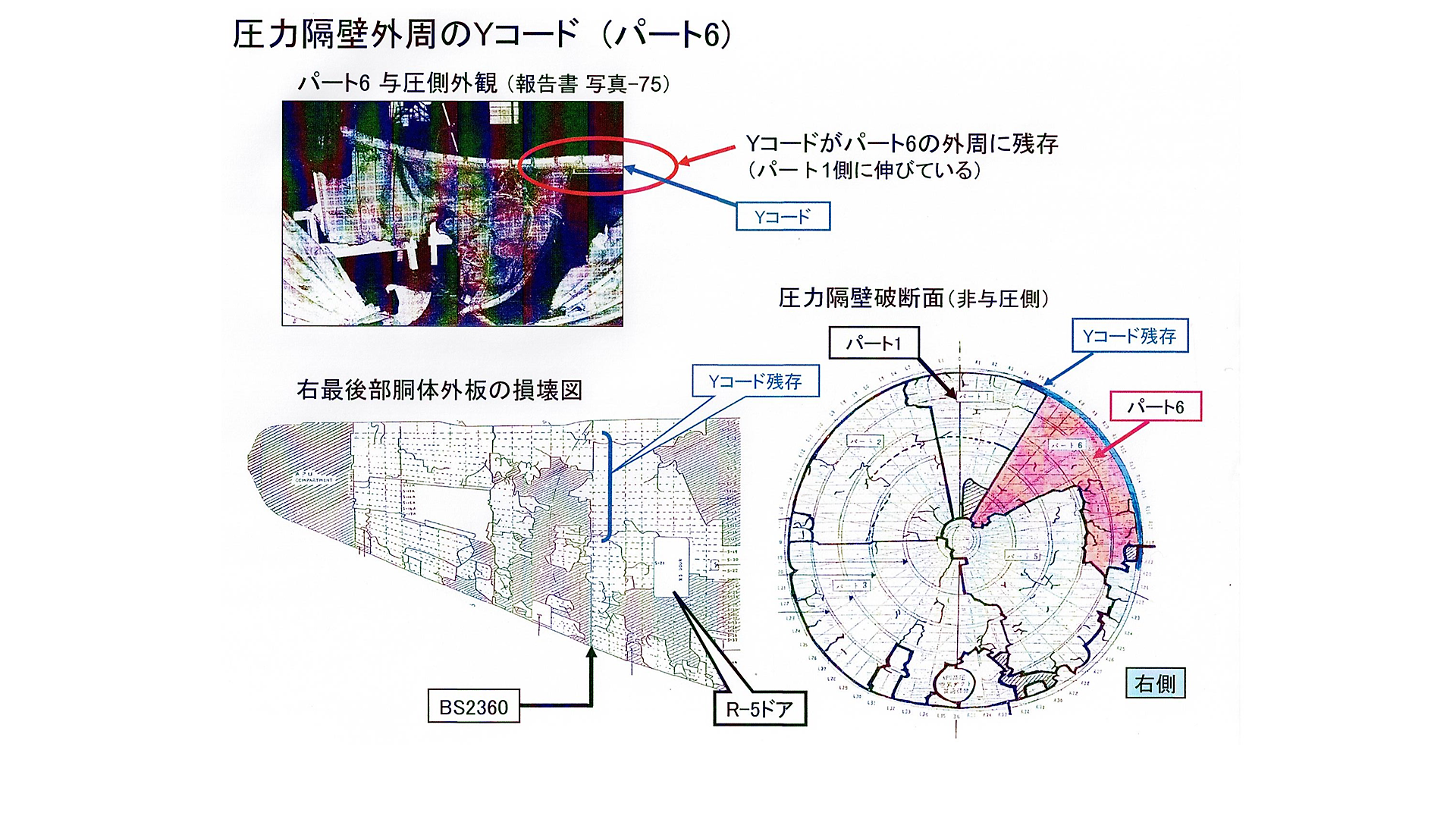
The figure shows a photo of the report and a cross-sectional view of the right rear fuselage and pressure bulkhead.
The bowl-shaped rear pressure bulkhead is installed along the circumference of BS2360.
First, pay attention to the break line around the pressure bulkhead in the "damage diagram".
There is a place where the outer panel is broken linearly back and forth with BS2360 as the boundary. This line is the boundary between pressurized and non-pressurized. Since the vicinity of this line was the fulcrum of bending of the fuselage skin, it becomes a line where bending fatigue was repeatedly concentrated.
There is a point that suggests the location of the gap where there was an air leak. On the outer circumference of Part 6 of the pressure bulkhead cross section, there is a part where the mounting bracket of the pressure bulkhead called the Y-chord shown by the blue line is attached to the pressure bulkhead side and remains. It is a unique appearance feature.
The presence of the Y-chord on the pressure bulkhead side indicates that the Y-chord has peeled off from the fuselage skin. According to the photo, the belt-shaped Y-chord circled in red is reflected, and you can see the situation where the range of peeling extends from Part 6 to Part 1 side to near the top of the fuselage.
The Y-chord on the pressure bulkhead side is in a state of being peeled off from the outer plate, suggesting that a gap has occurred here.
It should be noted that this part is just behind and above the R-5 door at the rear right, which corresponds to the place where "destruction of the R-5 door ceiling" was confirmed in the conversation between the room crew and the flight engineer.
One of the survivors testified that something like cloth was fluttering behind the ceiling. The air leak did not stop completely, but a small gap remained, indicating that a very small amount of air continued to leak even after the time zero.
This fact proves that there is no big hole.
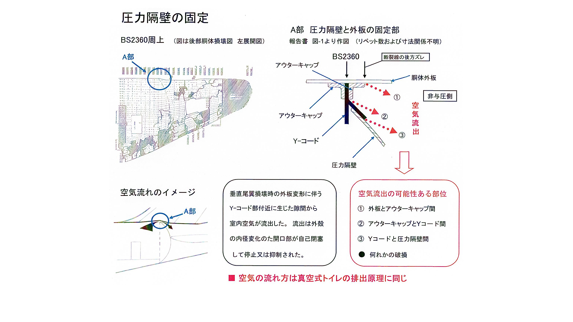
Next, observe where the gap occurred around the Y chord.
The Y-chord attachment in this figure is transcribed from Figure 1 of the report.
There are four possible routes for air to pass near the Y code: ①②③ and any other damaged part.
From the situation of the wreckage, the possibility that the Y-chord remains and a gap is created between it and the outer panel seems to be the highest in route ①. The relationship between marbles and lemonade bottles mentioned above is the most compatible in ①.
According to the "Supplementary Structural Inspection Guidelines" of the B747, it is stipulated that the Y-chord inspection should be carried out every 30,000 times, and the inspection is virtually free from the normal number of flights.
There is a recognition that Boeing is such a sturdy part, and I think that the image of a failure in this part was originally a blind spot. This recognition may be the background that Boeing intuitively turned to "cause = tearing of the pressure bulkhead".
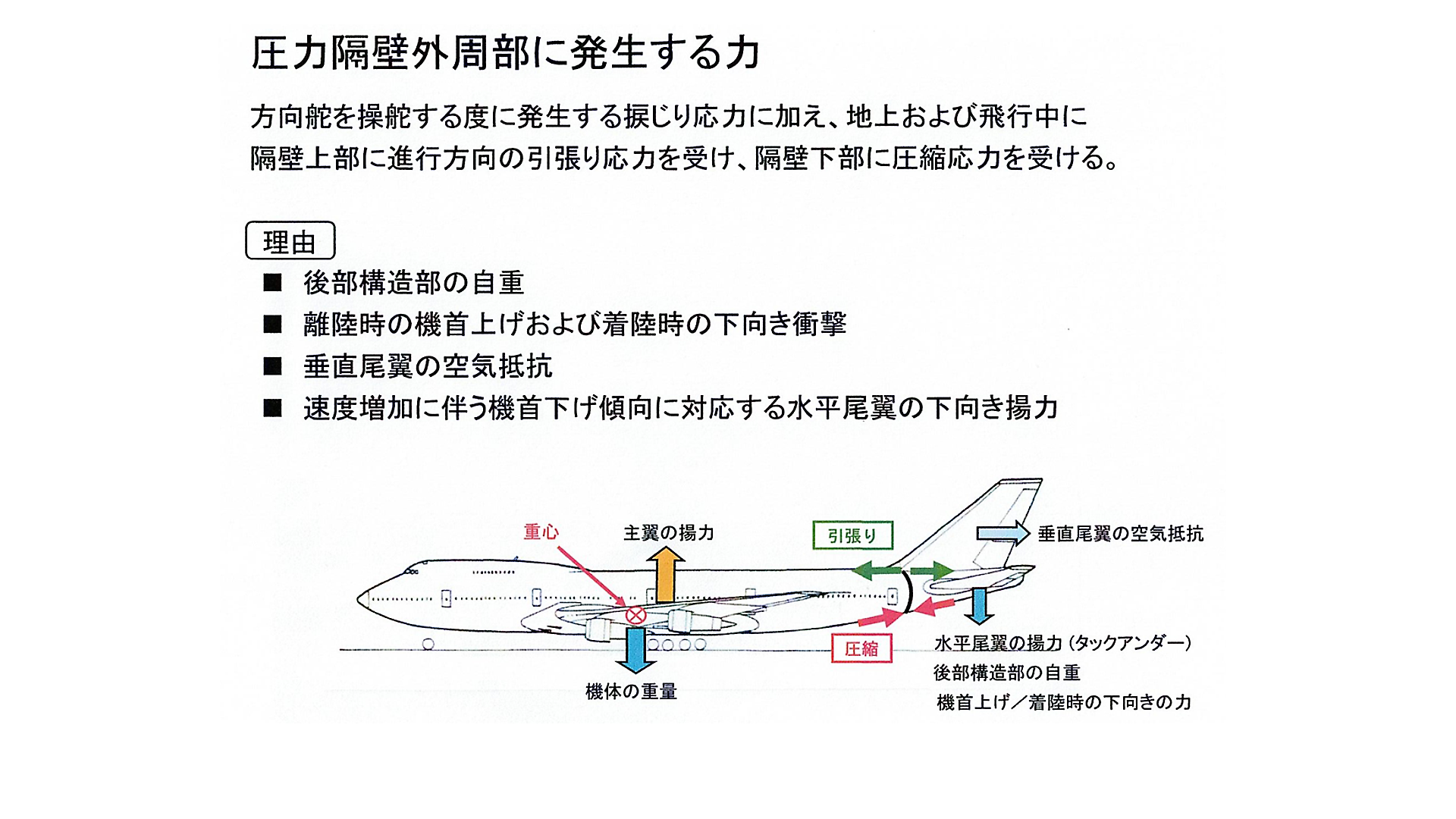
With a little more consideration, The upper part of the pressure bulkhead receives the tensile force in the traveling direction as shown by the green arrow in the figure, and the lower part receives the compressive force in the traveling direction as shown by the red arrow.
The reason is due to various downward forces acting on the rear of the aircraft. for example, Downward force due to the weight of the structure, downward force at takeoff, downward impact force at landing, backward force due to air resistance of the vertical stabilizer, and horizontal stabilizer that balances buoyancy and gravity during flight. There is downward lift, etc.
These forces and the rudder-derived forces are concentrated around the pressure bulkhead, especially above the bulkhead. There is a high probability that a tear will occur in the upper part of the pressure bulkhead mounting part. I can imagine that the upper part of the pressure bulkhead and the outer panel are more likely to peel off and create a gap.
The position of the Y-chord still connected to the pressure bulkhead is the same as the position near the top of the R-5 door, and I don't think this sign is a coincidence. It is probable that a gap occurred at this point.
The fractured appearance of the fuselage skin is a straight tear line in the upper half, which is clearly different from the lower half that was replaced at the time of repair. I think that the upper side is constantly receiving the tensile force, and the lower side is the difference in the history of constantly receiving the compressive force.

